
In this Chapter (page 145) I suggest that it is not necessarily easy to create an FTA that provides insight and is easy to understand. On page 156 I have written about the development of understandable fault trees. The purpose of this note is to illustrate these points, using what at first sight appears to be a simple and common electro-mechanical device, a gas fired oven. Such devices are designed for controlled combustion, but have the potential to explode if an explosive gas-air mixture is created in the absence of an ignition source.
One way of approaching FTA construction is to simply say that all electro-mechanical devices, being controlled by people or by electronics can have their failure expressed in a generic manner such as this:

Diagram 1
The mechanical failure can be then analysed further according to the components and the way in which they are related as in fan failure and gas valve failure. Electrical system failure may be a reason for a mechanical failure: Fan failure could be because the fan stops due to electrical failure, or because the motor fails or because the inlet is blocked. Similarly, control system failure could be due to electrical supply failure or to actuator failure (fan switch, gas valve actuation). In this case, electrical failure may be a common mode failure for both the mechanical components and the control system. Generally it will be necessary to consider both power voltage failure and control system voltage failure as the two may be at different voltages and possibly from different supply circuits.
The previous generic scheme for an electro-mechanical system FTA could be recast in this way:

Diagram 2
Control systems, however, whether automated, computer operated or human have certain similarities and their failure can be more usefully understood and modelled as follows (Table 9.3 refers):

Diagram 3
Perception is the process of detecting a signal and communicating it to the brain (in the case of a human being) or to the central processing unit (CPU) of a computer or the logic devices of an automated system. Cognition is the process of deciding what the perceived signal means in the context of time or the presence of various other input signals and any necessary voting logic when inputs are duplicated. The brain, CPU or automated controller makes this decision to act in a certain way or not act. Its effector output is the action taken, which could mean the opening or closing of a valve for example. The effector output includes everything needed to give effect to the intention formed by the cognition process: the generation of a signal to the actuator, transmission to the actuator and the response action of the actuator. The actual state of the actuated component (eg. the valve position) could be sensed and become an item that is subject to perception by the control system. Alternatively, there may be no actual feedback of the actual component state. Where this state is significant for safety reasons, it is likely to be indicated to the control system.
Seen in this light, a FTA for any electro-mechanical system can be built quickly with only as much complexity as is introduced by the system design and the nature of the control system: eg. how many components provide the perception capability and what exactly does each do?
What follows is an example of a very simple oven with no complex controls. In a thermodynamics laboratory used by second year engineering students, there was a small oven designed for student use to demonstrate thermodynamic principles. Its operation was entirely manual and there was a sight glass to allow the student to check for the presence of a flame. There were no written instruction on how to, or how not to, fire up the oven. Even the staff were not too sure. As might be expected, one day a student incorrectly opened the gas valve and fiddled around for the igniter button while starting the air flow. There was a muffled explosion from within the oven and the sight glass flew across the laboratory and embedded itself in the concrete blocks that made the wall. The student was shocked as the glass could so easily have penetrated him. We quickly wrote a procedure and displayed it on the wall of the oven.
The same problem could arise in an automated system if the intended sequence of actions did not happen, and when you think about it this could be either because of a delay in air flow operation or because of a failure of sequencing (gas valve before air flow instead of vice versa) or timing (the sequence should perhaps be air flow operates at t seconds, and igniter operation at t+4 and gas flow at t+8, but possibly the igniter fails to operate or the gas fails to ignite). In diagram 1 above, all of these options are simply a Control System Failure, being either:
-
Perception, if for example the air flow rate is detected
-
Cognition, if for example the timer fails
-
Effector Output, if for example the command to operate the igniter is not successful.
This seemingly simple case shows clearly that a detailed understanding of what produces the Top Event is valuable before constructing the FTA itself. Simply expanding the logic of diagrams 1 and 2 above will not necessarily do this.
However, another way of looking at the development of a FTA is to approach it via the questions suggested on page 148.
Step 1 – The Top Event of interest is energy-based and the energy source is the chemical bonding energy of the fuel gas
Step 2 – The Mechanism Division of interest is Unintentional
Step 3 –
Question 1: The ability that the system has that normally prevents an uncontrolled (in this case) release of chemical bonding energy of the gas is the ability to avoid explosive gas/air concentrations such that the gas burns at the burner nozzle and an inadvertent possible explosive mixture is not formed or ignited.
Question 2: The mechanisms that provide this capability need to be –
-
A means of controlling the flow of gas
-
A means of controlling the flow of air
-
A means of igniting the gas in the air
-
A means of control of the amount of gas and air flows and of the sequence of flow and the timing of ignition in order to avoid explosive gas/air combinations or the circumstances in which they could arise. This depends on control system logic.
How are these mechanisms provided?, Let’s assume, respectively:
-
A connection to a gas main and an electrically-actuated gas control valve
-
An electrically-powered fan and airflow control through an electrically-actuated exhaust damper
-
A electrically-powered spark igniter
-
A computer control system with feedback of gas control valve position, exhaust damper position and flame detector and inbuilt logic and timing requirements to provide the ability to manage potentially explosive situations.
To further understand the qualities of some of these mechanisms, we need also to consider how the system has been designed. For example, it is likely to have been designed with the type of equipment safety provisions described in Chapter 12 (page 212), so that on power failure its gas valves are intended to close (power is required to hold them open) and the exhaust damper to open (power required to close it).
From this we can understand something of the relevant failure modes of these components. For the gas valve, the failure mode of interest is either the valve stuck open in the event of power failure or a gas valve that fails to close when the control system commands it to do so. In addition to these full movement failures, the gas valve could fail to stop the passage of gas even when it has closed. Such a failure could be due to something blocking the movement of the valve or to wear of the valve seat. The failure mode of the exhaust damper is that it remains closed when it is signalled to be open or fails to open fully. Even if the controller is aware of this, as it would be, there is no further action it can take that has not already been attempted, eg. it will have been commanding the fan to be on.
It is necessary to also understand how the Top Event could arise, so I will provide a hypothetical explanation here, which I hope is not too far off the mark, given that I don’t have any personal experience with the design of such systems.
Overall, an explosive atmosphere could arise in these situations:
-
At start up, the expected sequence (which may be of air flow, followed by igniter actuation followed by gas flow and confirmation of flame) does not occur. The igniter may fail or ignition of the gas fails and the expected response (which may be to interrupt gas flow, allow the chamber to clear with continuing air flow and then repeat the start up sequence) does not occur
-
Under normal operations, the flow of air is reduced below that required, leading to incomplete combustion and possible flame-out and this is not recognised and responded to or the flow of gas exceeds that which is required and is unsuited to the air flow rate.
-
Under normal shut down, the flow of gas is not fully stopped, resulting in flame-out also leading to an increase in gas concentration inside the oven.
(The example above is of the first explosion scenario listed above. The control system, such as it was, relied on operator behaviour for the correct sequence to occur.)
This logic is expressed in the analysis that follows, in which X is used to indicate the ‘OR’ logic.
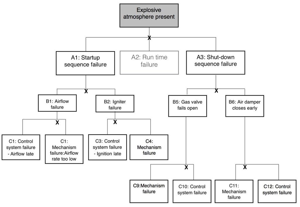
Diagram 4

Diagram 5
You will note that the meaning and logic of the analysis is quite clear when it is done in this manner. The analysis can be extended by including expansions of the various mechanism and control system failure boxes. In traditional FTA, mechanism failures are regarded as either of a primary, secondary or command types (Figure 9.6, page 153) and each Mechanism Failure box would be expanded to allow for each of these. It is worth noting that command failures are not necessarily limited to control system failures. For example, when maintenance is undertaken, someone might isolate the blower motor for the oven and not reverse this before an attempt is made to start the oven. The fact that the meaning and logic of the analysis is evident also means that the failure modes of interest in the analysis are evident. In fact, an FTA derived in this manner can be thought of as an extension of Failure Mode and Effect Analysis. The FTA brings together the failure modes of interest in relation to the top event.
Why attempt a FTA for this system?
Having gone through this analysis one might well ask ‘why do this?’.
Either one pursues the FTA because one needs a detailed understanding of the how (that is, Mechanism) things could go wrong (which I think an understanding of the physics and chemistry gives us and words are able to state, not FTA logic diagrams per se), or because someone wants to know the probability/frequency of the top Event. One could and probably should ask, why do you want these numbers? Perhaps they don’t really know but think it sounds good to ask.
In the case of a public planning decision, such as in the placement or modification to a high hazard plant such as a petrochemical refinery, it will be a valid requirement, see Figure 8.1 page 125. Otherwise it is only justified for a ‘could do’ risk control option (page 125), to establish the cost vs benefit of the proposed changes . In any other situation, the only matter of real concern is how well the control measures have been thought about and implemented. In a case such as this, the logic of the control system, the need or not for the control system to include actuator feedback, the quality of the control system electronics etc. will in all likelihood be determined by codes of practice or standards (‘Safety Integrity Level’ page 217) – in other words become a ‘must do’ or ‘should do’ control measure. Probability estimates in this situation are of academic interest.